We are Leading Dimensions Slip On Flanges & Stud Bolts ASME B16.5
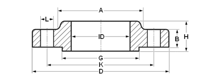
| CLass | 150 | 300 | 600 | 900 | 1500 | 2500 |
|---|---|---|---|---|---|---|
| DIA A | 30 | 38 | 38 | 38 | 38 | ... |
| DIA D | 90 | 95 | 95 | 120 | 120 | ... |
| THK B | 11.2 | 14.3 | 20.7 | 28.7 | 28.7 | ... |
| DIA G | 35.1 | 35.1 | 35.1 | 35.1 | 35.1 | ... |
| DIA K | 60.3 | 66.7 | 66.7 | 82.6 | 82.6 | ... |
| H | 15.6 | 22.6 | 28.4 | 38.4 | 38.4 | ... |
| NO. L | 4 | 4 | 4 | 4 | 4 | ... |
| DIA L | 15.9 | 15.9 | 15.9 | 22.2 | 22.2 | ... |
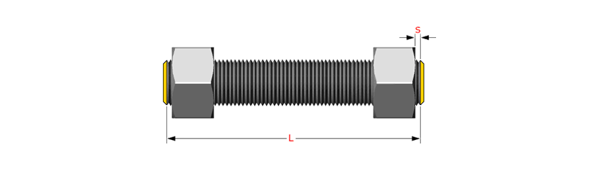
| Stud Bolts Diameter x Length | ||||||
| DIA (in) | 1/2 | 1/2 | 1/2 | 3/4 | 3/4 | ... |
| lgth (mm) | 55 | 65 | 75 | 110 | 110 | ... |
Notes
- Dimensions are in millimeters unless otherwise indicated.
- The length of the Stud Bolt does not include the height of the chamfers (points).
- The length of the Stud Bolts includes one Spiral Wound Gasket with a 4.5mm thick sealing element, which is compressed to 3mm while tightening the Raised Face flange connection.
- ID = Depending on the wall thickness of the pipe, must be specified by the purchaser.
- Important! please read this short article
Dimensional Tolerances of Slip On Flanges ASME B16.5
Outside Diameter *
Tolerances not listed in ASME B16.5 2013
≤ 24 = 1.6 mm
> 24 = ± 3.2 mm
Tolerances not listed in ASME B16.5 2013
≤ 24 = 1.6 mm
> 24 = ± 3.2 mm
Inside Diameter
≤ 10 = ± 0.8 mm
≥ 12 = + 1.6 mm / - 0 mm
≤ 10 = ± 0.8 mm
≥ 12 = + 1.6 mm / - 0 mm
Outside Diameter of Hub
≤ 12 = + 2.4 mm / - 1.6 mm
≥ 14 = ± 3.2 mm
≤ 12 = + 2.4 mm / - 1.6 mm
≥ 14 = ± 3.2 mm
Diameter of Counterbore
Same as Inside Diameter
Same as Inside Diameter
Drilling
Bolt Circle = 1.6 mm
Bolt Hole Spacing = ± 0.8 mm
Bolt Circle = 1.6 mm
Bolt Hole Spacing = ± 0.8 mm
Eccentricity of Bolt Circle
≤ 2.1/2 = 0.8 mm max
≥ 3 = 1.6 mm max
≤ 2.1/2 = 0.8 mm max
≥ 3 = 1.6 mm max
Thickness
≤ 18 = + 3.2 mm / - 0
≥ 20 = + 4.8 mm / - 0
≤ 18 = + 3.2 mm / - 0
≥ 20 = + 4.8 mm / - 0
Length thru Hub
≤ 18 = + 3.2 mm / - 0.8 mm
≥ 20 = + 4.8 mm / - 1.6 mm
≤ 18 = + 3.2 mm / - 0.8 mm
≥ 20 = + 4.8 mm / - 1.6 mm
Diameter of Contact Face
1.6 mm Raised Face = ± 0.8 mm
6.35 mm Raised Face
Tongue & Groove / Male-Female
± 0.4 mm
1.6 mm Raised Face = ± 0.8 mm
6.35 mm Raised Face
Tongue & Groove / Male-Female
± 0.4 mm
Studs are measured parallel to the axis (L) from the first to the thread without the chamfers (points). S = free threads equals 1/3 time bolt dia
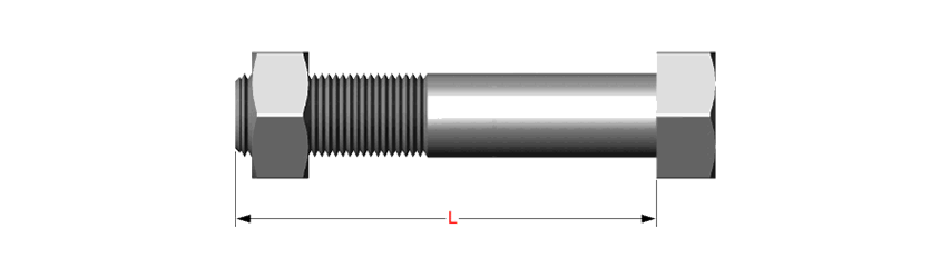
Hex bolts are measured from under the head to the end of the bolt